Are you still new to final drive motors? Are you having some trouble with the terminology? In Part 1 of our terminology series, we'll be talking about the basic specs for a final drive, exterior anatomy, hydraulic connections, and brakes.
.png?width=600&name=Terminology%20for%20Final%20Drive%20Motors%2c%20Part%201%20(1).png)
Here are a few Shop Talk blog posts you might be interested in:
Specifications
The torque for a final drive motor is what enables the wheels and tracks to turn. This is very different from speed, and their relationship is inverse: the higher the speed, the lower the torque, and vice versa. This is where the speed reduction ratio comes into play: the planetary gear system is designed to reduce the speed provided by the hydraulic motor so that sufficient torque can be generated to move your equipment, even when carrying heavy loads or digging into the ground. The speed reduction ratio may also be called the torque multiplier.
Exterior Anatomy
A final drive core refers to the final drive as a whole with all the parts it contains. A final drive motor has a hydraulic hub and a planetary hub. The hydraulic hub (or hydraulic side) contains everything related to the hydraulic motor and is filled with hydraulic fluid. The hydraulic lines needed to run your final drive connect to ports on a valve block securely attached to the hydraulic hub.
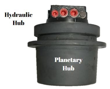
The planetary hub contains the planetary gear set that multiples the torque generated by the hydraulic motor. It is filled with gear oil and is accessed by removing the cover plate.
Hydraulic Connections
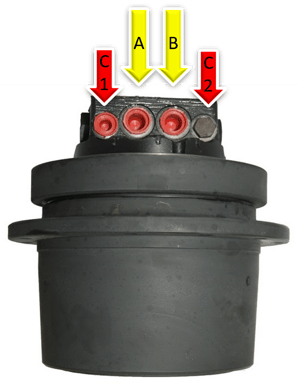
Every final drive has at least two ports/lines: flow port and return port. These are going to be the largest ports. Some final drive motors will also have one or more case drain ports that, depending on the model of machine you have, could have an inline case drain filter. If a final drive has a braking system, then it will have a separate brake port. For multi-speed final drives, there will also be a dual-speed port.
In this figure, the flow and return ports are labeled A and B, respectively, while the two case drain ports are labeled C1 and C2. You will notice that in this drive motor only one case drain port is being used.
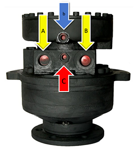
In this drive motor, the flow and return ports are again labeled A and B, with the case drain port labeled C. In addition, there is a brake port labeled with a lowercase b.
Brakes
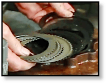
The brake assembly is comprised of several parts, starting with the brake housing. The brake housing, as shown below, has gear teeth (or splines) on the inside surface. The assembly also includes a very large Belleville washer and a brake piston. The brake pack, or brake stack, is made up of brake disks, spacer plates, and shims.
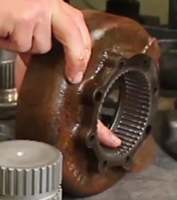
Brake disks have gear teeth on the inside and mesh with the upper drive shaft, rotating with it. Spacer plates, on the other hand, have gear teeth on the outside and mesh with the inside of the brake housing. There may also be shims between the brake disks to achieve the correct height of the brake stack.
Conclusion
If you're new to final drives, the terminology can be tricky to learn. However, for those of you more familiar with them, do you have any comments on our definitions here? If so, leave them in the comments!